
This little unit has been a project that started back in 2017 and still under developement now.
The Sidbox was a device I dreamed of having ever since I began really making robots and electronics with microchips, The PIC Microcontroller. The first chip I tried out was the PIC16F88 – A very powerful little 8bit chip running at a maximum of 8Mhz and all I made it do was communicate over the serial port and blink lights.
Then the dsPIC24 which could go up to 70mhz which allowed me to generate more complex noises, and when suddently I made it do a PWM sound. This sounded much like the SIDchip and blew my mind, I was able to make a device that sounded like the C64! Only with one channel, it took me weeks to work out how to mix the other audio channels to gether thinking that mixing audio together in binary had be way complex. Imagine my FACE PALM when I realise was…… “no, you do actually just ADD them together”
AudioOut = Channel1 + Channel2 + Channel3 then device this all down to fix into an 8 bit output and then BOOM I could hear all 3 channels working! Granted it sounded grainy and the fidelity was more toilet than amazing. BUT the curiosity began to burn, “What if i could have something external update these channels.” So I made my first sid chip, capable of 3 channels, PWM and SINWAVE (non of this triangle wave nonesense) So when this worked via streaming uart data and address. I converted it to a USB and wrote my own software for it.
THIS is how it sounded.
This is a result of painstaking coding in visual basic, a windows 8 OS and months of fine tuning. Eventually the software was created and performe much as you’d expect with registers and data being streamed from the software into the sidbox chip.
The USB hardware took some work to get going too since windows 8 drivers for Human Interface Device was pretty buggy so things like streaming had to change to streaming into a USB buffer, from there to the USB Sidbox.
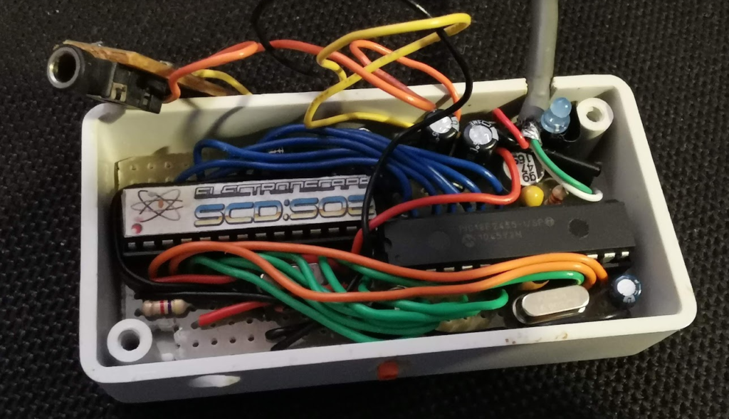
Here is a picture of the USB SidBox
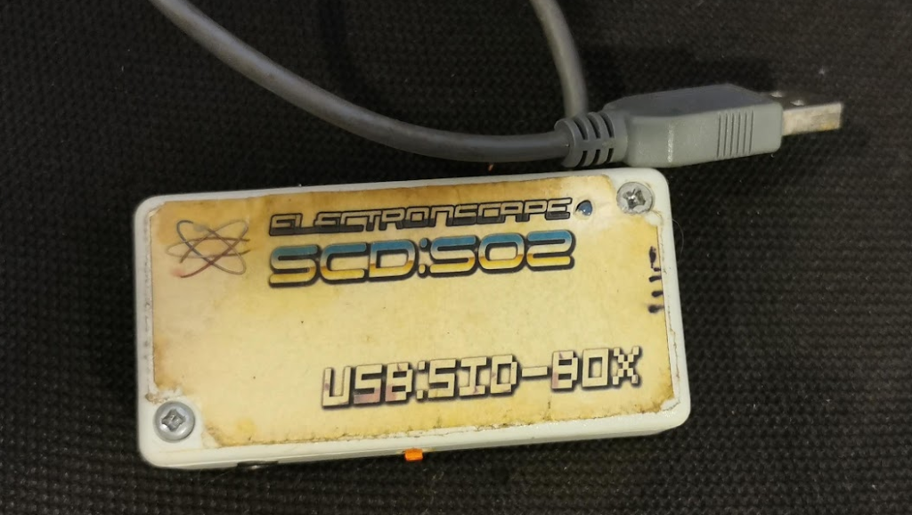
The SCD:502 that is my Sidbox on a chip, Sound Chip Device, 502 meaning the PIC24HJ128GP502-I/SP
which is found here : Farnel
I plan to release the source code to this little thing, but please be warned its messy and not well documented and is not supported by anymore.
The controller chip is a PIC18F2455 for the USB to registers and data out and clock pulses, this is massively buggy in the USB driver side, while the chip does its best to cope with windows 8/10 drivers, windows 11 is not getting a test as personally windows 11 is far from a finished OS.
This sound chip was capable of SawTooth, SineWave, Triangle, and SAMPLED sounds. I preloaded some samples into this chip but are replacable through the software.
After I got my information from this chip so moved on to working out more with a chip that could display stuff.
With the discovery of the SSD1289Z display LCD, it was a 65k colour display with a strobe type interface I came up with something like this
This got REALLY exciting, I created a prototype board with this and created a very very buggy and annoying reboots everywhere and used it for a few months.
The compiler for this at the time was a derivative of C and it made compiling a pain as sometimes gave different results. But it was the only compiler I had, this was before the days of Microchips IDE and MPLABX compilers. So after I had a semi stable version, I started to take it out to places for me to relax and view the town with nostalgia pumping into my ear boxes 😉
THEN I discovered the 32 bit PIC, which my compiler could do… but badly, after frustrations of the SID 8580 engine failing to run some songs, but perfect with others, I tested my code on Windows C compiler, the CodeBlocks with the GNU GCC compiler. It is free and fast and regularly updated.
SO I copied my code, MINUS the display parts and the songs that wouldn’t work before … THEY WORKED, and not only did they work, they sounded WONDERFUL almost true to the 8580 I just put in some bad filter values and tweaked them until I was sure I had it sounding close to the real 8580.
After this, I had to “purchase” the compiler from Microchips to compile the code at real speed and sizes, GCC is meant to be free, just doesnt make sense for this- but i worked on renting the compiler for months.
SO after I coded this pic32 chip using the compiler from Microchips I uploaded the firmware, and nothing!
NOTHING WORKED! Gutted and frustrated that I had purchased this compiler…….. OH WAIT.. perhaps if I disconnected the programming lines…….. AHH THERE SHE GOES!
The boot screen to see that was great. And to my suprise, the sidbox ran 10x FASTER! so this compiler I thought at the time…… WORTH IT (that changes down the line)
So the Sidbox V1.2v was showing
With the more CPU power, and speed, I was able to increase the PWM audio output to generate a much higher output frequency and reached FROM 22khz to a cripst 48Khz, on the same chip with from the old C compiler to the one I purchased.
So I can continued code this and improve on this, and this is where I met Maddi, MsMadLemon As we spoke about the unit and what I was doing with it, we both where more into the retro and the stuff we liked to do as kids, and joking around.
As the Sidbox Project got traction Maddi added her input along the way with tweaks and features that would improve the sidbox more.
SO the Sidbox V3.2 was half way built this had a much faster chip on it, but sadly this still was using the PWM output with a 100Mhz chip but still did the job but its audio was heavily interfered with but the badly designed PCB and ground loop… (Basically a constant buzzing sound from the LCD going right into the OP AMP audio)
THE SIDBOX V4.2
This is where it began to gain much more love.
Using the PIC32 with 280Mhz at the time this machine did everything we wanted.
I would suguest to read more here MsMadLemon has written a comprehensive blog about the project here
THE SIDBOX V5.2 (LATEST REVISION)
This machine uses the STM32H743 and this runs at 480Mhz, this opens the doors for a lot more functionality, more tunes more ram, external SDRAM access for EVEN MORE space.
Faster SDCARD access but to stay inline with the SDCARD usability its a 1bit data transfer still pretty slow but the files that are intended on the sidbox are usually fairly small.
The new features includes a slightly bigger screen with more pixels, instead of the 320×240 at 3.5 inch this sports a 4.2inch 480×320 LCD size, bigger area MORE data and higher resolution. Still a resistive touch screen but this turns out to be pretty good for what its needed for. The intention to use the hardware buttons to navigate the screen is going to be a full feature but touch screen is there for convenience.
This new device has a built in C64 style computer, the Mica computer, it emulates the 6502 (not the 6510) a semi compatible VIC chip and some memory locations are different to that of the C64, however this Mica system uses 2 SID locations too.
Any 6502 assembly language will generate code that will run.
I will be creating a memory address bank to reference up. And this is fast enough to play games and run demos.
As you can see this one runs on the CRT output, because our NEW Sidbox has a RGB colour CRT output also. Its up to you which output you want to use, as the Sidbox has a control setting that allows you to choose which display output you want to use.
And this next video shows the ability to use a keyboard with the sidbox too (tho thought will be a peripheral interace required as we didnt want to have a bulkier Sidbox.
TAPE LOADING
One of the features the sidbox has is TAPE LOADING
With this feature we’re able to load up games on the C64 (and C16 as tested before) and the Sinclair ZX Spectrum.
The ZX Spectrum loader has a few extra things it can do though, as some games expose the screen$ instruction and memory locations to where the image while loading is shown. So I have tapped into this while the process is being done.
As you see this tapeloader is showing the image and loading it in and also passing the information out to the ZX spectrum too.
Not all games work like this though, as some games are compressed, loads into random areas of ram then copied to the screen memory for that fast “DONE” look – I personally prefer to see images loading up like this 😉 shows that its doing something.
SOUND PLAYERS
This system has now a DMA system so this means I am able to process tracker information mixing tracks up while the DMA takes care of the audio transfer, this leaves the CPU to do a lot of work while it doesnt worry about transfering data to the DACs (this STM32 has two DACs 12bits) which is wonderful sounding and accurate!
The current status of the players are
- WAV (most formats, 8 and 16bit, mono, stereo, 8khz to 48khz)
- SID (our amazing sid chip, which now contains a 6581 and a 8580 – WHICH is customisable too! so you may have been one of the few with a 6581 with extremely strong filtering…. SO this allows you to adjust for how you rememeber it!)
- MOD (The amiga 4 channel pro-tracker mod, this version is capable of have 8 channels though – found a song that actually uses 8 channels in a pro-tracker mod!? HOW was this done before ?? LET ME KNOW!!)
- YM (these are streams of pre-recorded registers from the Atari ST YM chip, however for ease of use, the sidbox uses these and generates the sounds!)
- S3M (This was one of the trackers used in Unreal Tournament and the game it self again I only just got this to work and would only work on 8bit at the time – THIS chip allows for bother 16bit and 8bit samples!)
THE NEW PLAYERS added.
- STP (Sound tracker 2 Pro – while not strictly completed the file system now plays these, had a lot of trouble with this one at first – but its there and now working!)
- TFMX (Turrican music was an absolute favorite of mine. Was one of the first tunes I heard from the amiga 500!)
- AY (These are used mostly for the Spectrum ZX, but sadly the ALU Buzzer output is still a little buggy! I may have to start from scratch with this on)
- POKEY (The Atari 800 with the POKEY chip, responsible for not just the sound but other bits too – However this was a question Maddi would ask about a number of times and I really scratched my head on this one to make it work! But there it is… and it not only just plays SAP files. It will play the sub formats too, CM3, MPT, FC, CMR and TMC)
- VGM (This was the dream of mine to have working, and was super difficult to do, MegaDrive (Genesis) and MasterSystem/Game Gear music) This was tough to do and still insisted on a lot of CPU processing, the LFO and synth and mixing this Yamaha chip did for the megadrive! however after much optimisations it works, but it still does steel a few too many cpu cycles and the screen does jitter sadly: BUT Sonic the hedghog though! so WIN!)
- MED (This was one of my fave trackers when writing music for my games, they where written in BlitzBasic 2 and its music tracker for MED was much more controllable, the routines for the MED play back was simpler than I thought, I just copied the pro-tracker code, got the med loader to place the tracks in memory correctly and tweaked the code to sund right. Its not strictly specification accurate so im expecting some issues along the way though)
SO WHAT INSIDE THE BOX?
The current specifications for the Sidbox:
- CPU : This is a microcontroller, the STM32H743 @ 480Mhz
- RAM 1: This is 512k of internal memory, this is used for the DMA and audio processing and the screen blitting processes.
- RAM 2: 8 Megabyte of SDRAM running at 133Mhz. This is purely used for storing the music files/ graphics and audio data that then gets pulled into the RAM 1 for faster processing.
- AUDIO: 2 12bit DACs, voltages of 0v – 3.3v which is fed into a TDA2822 (the same on they use in the GameGear!) but it produces a much cleaner, buzz free and LOUD output. Headphone wearers might want to be careful with this. An internal speaker would take up too much real-estate and sadly cant be included. The audio amp will however sync to a LINE OUT.
- Graphics: This uses the onchip Graphics accelerator. This takes two bitmaps and overlayes and mixes the colours correctly. IT also runs through the DMA so anything in the external ram and internal ram is both pushed on to the LCD output without the CPU requirements, All the CPU does is tell it where it wants a pixel! pretty incredible for this chip!
- LCD: This offers up a 480×320 at 65K colours… However the Sidbox has a choice out of 256 colour indexes of which these can be changed at anytime to offer up any colour from a palette of 16 Million!
- CRT: This is an RGB 15khz output with a vsync pulse which outputs just a basic colour output, so basically, 16 colours, 8 bright, 8 dull. This was required as the technique for displaying the colours was non standard, since we’re using the accellerator for the LCD and the CRT output pins dont have a DAC. So each colour data is a stream of 1 bit data from an SPI output pin, so we have 4 of these, allowing the RGB output port to combin the colours later. This needs some work though as the latching of the colour streams can go out of sync slightly causing a teeny glitch but more than viewable.
- Hardware Buttons: These are available for navigating the screen if you choose to. These hardware buttons are also related joystick port which doubles up as a mouse port also depending on what application is needed.
- SDCARD: Currently this only supports up to 8GB, and FAT32 with short names officially, without breaking some Microsoft Rules. Long names CAN be done but without a modification to the flash rom.
- USER PORT: This is port to which there is a UART Serial interface available and audio outputs direct from the DAC, so you can bypass the TDA2822 amplication altogether and get direct from chip sound. A digitial Tape output signal so as to drive a Neelix Adaptor directly if you wanted. It also Contains the RGB and SYNC outputs for the CRT also 15Khz (when switched on)
Thank you
Thank you for reading all of this if you managed it! There will be more information added later and I will add them to THIS stream below.
I love this projekt!
Thank you!!! it still work in process, but wow the prices for the processors are stilly too high :/
Thank you!